30+ proximity sensor block diagram
Connection diagram GKey with Tina 2 to Pluto Reset Separate unlock cable Knox2A English - pdf - Connection diagram. PWR SEAT FR.

30 0 30 Volt 500w Switching Power Supply For Power Amplifier Youtube Power Supply Circuit Power Amplifiers Circuit Diagram
The power-units are supported through power scavenge units like solar cells whereas the other subunits depend on the application.
. Stop lights high mounted stoplight brake system driver support system vehicle proximity notification system. A wireless sensing nodes functional block diagram is shown above. Refer Block Diagram of 555 timer IC given above.
This circuit can be built with electronic components like a capacitive sensor R1 220K R2 47K R31K D1TIC106M 600V 5A SCR LP1is any small Neon Bulb LP2 is 230V Lamp BZ1 is 230V Buzzer Optional SPST SW1 Optional and PL1 is a Male Mains plug and cable. The user needs to diagnose the sensor and if necessary replace it. The cause of the problem may lie in the sensor itself less often in its wiring or poor-quality contact.
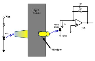
AS7341 Block Diagram English Factsheet AS7341 Auto White Balance. The sensor node can be connected to the network with the help of a transceiver unit. D represents that the primary winding adopts triangular form wiring Y represents the secondary measuring winding adopts star form wiring n represents to lead the neutral line 11 represents that the secondary winding phase angle lags.
OCB sensor connection block. Dyn11 is ATO step updown isolation transformers wiring method. P0948 Malfunction of the control system of the solenoid valve for regulating the oil pressure.
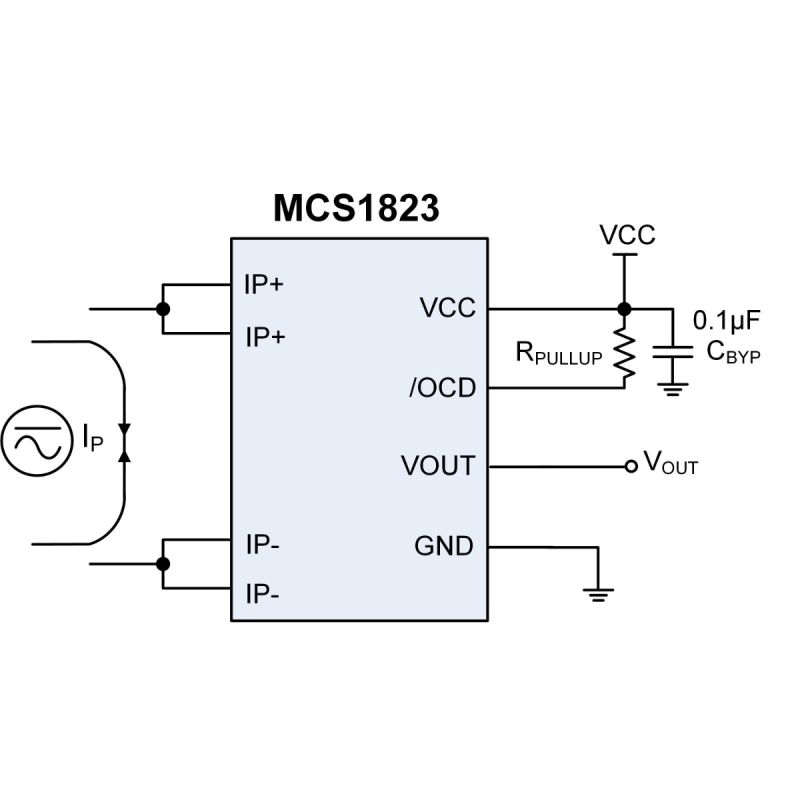
Simplifying your sensor connection for OSSD and voltage free safety sensors. LKA system inside rear view mirror garage door opener yaw rate G sensor brake system electric power. ACS712ELCTR-30A-T Tape and reel 3000 piecesreel 40 to 85 30 66 Contact Allegro for additional packing options.
There are sensors designed for speed measurement that operate exactly as proximity sensors. The Mains-operated Capacitive Sensor circuit diagram is shown below. SourceLine Regulation In the block diagram the input line voltage has a nominal value of 230 Volts but in practice here are considerable variations in ac supply mains voltage.
Optical sensor spectral sensor flicker sensor light source detection AWB camera improvement color measurement color shopping color picking. Fri 830 am to 530 pm CET Rotterdam Science. Your email address will not be published.
Circuit is not working. June 30 2018 at 129 pm. Internal Block Diagram of IC 555 ElectronicsHubOrg.
Give link to making the ir proximity sensor. AMS Footer Contact Info. Dyn11 Wiring Method of 3 Phase Step up Step down Isolation Transformer.
The TCS3472 Evaluation Kit comes with everything needed to evaluate the TCS3472 color sensor. Leave a Reply Cancel reply. P1138 Malfunction of the fuel pressure controller.
06-07 LBZ LLY. Required fields are marked Comment. Phone 43 3136 500-0 Fax 43 3136 525-01.
RTD Resistance Temperature Detectors sensors. Tobelbader Strasse 30 8141 Premstaetten Austria. The thickness of the copper conductor allows survival of the device at up to 5 overcurrent conditions.
Fuse box diagram fuse layout location and assignment of fuses and relays Chevrolet Silverado GMC Sierra 1500 2500HD 3500HD 2007-2013Chevy GMC Duramax 06-07 LBZ LLY Forums. Function Block Diagram - Instruction List -. The terminals of the conductive path are electrically isolated from the sensor leads pins 5 through 8.
A proximity sensor has a switching frequency specification which limits its use to measure speed. September 28 2018 at 915 am. If there is only two number it means there is no multiplier Then you just read the value of the first two numbers in picofarads.
For new digital cameras a bigger sensor area captures better quality but requires larger-diameter bulkier lenses. Fuel injectors under intake manifold Camshaft position sensors CMP located at the front of each cylinder head Oil pressure sensor pass side behind alternator Knock sensors KS rear of engine under exhaust manifolds. 2007 Chrysler 300C 57L HEMI V8.
In the sensor node one of the essential components is a sensor node. In most applications the control input is not used so that the control voltage equals 23 V CC. How to determine which oxygen sensor is having trouble based on the check engine codes.
Bank and Sensor Locations. Full frame 35mm which is actually 36mm wide APS-C Micro Four Thirds 1-inch 117 and 125 Type. The evaluation kit comprises of a main controller board with a PIC microcontroller an industry standard USB 20 interface with an USB cable a TCS3472 daughter card plug-n-play USB HID class drivers software documentation and GUI software allowing users to control the color.
Laser Sensor Explained Types and Working Principles. Since this ac supply mains voltage is the input to the ordinary power supply the filtered output of the bridge rectifier is almost directly proportional to the ac. Here are various types of sensors used to communicate the different parameters to the controller.
Pretty easy jobyou will be done in less than 30 minutesLocated over the front spark plug on driver sideWait for the engine to cool down before doing this. The sensor can be a digital as well analog-type based on the type of signal it passes. The first two numbers describe the value of the capacitor and the third number is the number of zeros in the multiplier.
The internal resistors act as a voltage divider network providing 23Vcc at the non-inverting terminal of the upper comparator and 13Vcc at the inverting terminal of the lower comparator. When the first two numbers are multiplied with the multiplier the resulting value is the value of the capacitor in picofarads. This illustration compares digital camera sensor sizes.
Match The Right Sensor To Your Automotive Application Electronic Design
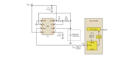
Use Analog Techniques To Measure Capacitance In Capacitive Sensors Electronic Design

How Track Circuits Detect And Protect Trains Greater Greater Washington Model Railway Track Plans Model Trains Model Train Layouts
Wiring Diagram For Parking Light Parking Brake Wires Kia Forum

Mechatronics Engineering Interfacing Lcd Without A Potentiometer In Arduino And Ccs Arduino Mechatronics Engineering Mechatronics
What Is The Difference Between An Npn Sensor And A Transistor Quora
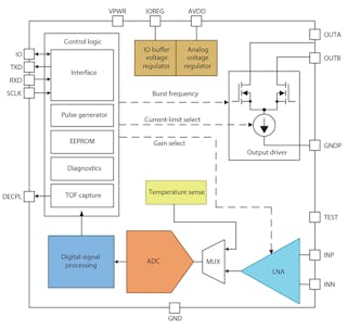
Radar And Ultrasonic Sensors Strengthen Adas Object Detection Electronic Design

Human Isl1 Ventricular Progenitors Self Assemble Into An In Vivo Functional Heart Patch And Preserve Cardiac Function Post Infarction Molecular Therapy

Advanced Building Automation Sensors Save Energy Enhance Safety Electronic Design
11 Myths About Hall Effect Sensors Electronic Design
Mcs1823 Linear Hall Effect Current Sensor With Over Current Detection In An Ultra Small Package Mps
11 Myths About Als Proximity Sensors Electronic Design
Wiring Diagram For Parking Light Parking Brake Wires Kia Forum
What S All This 555 Timer Stuff Anyway Electronic Design

This Article Briefly Describes The 30 Watt Audio Power Amplifier Irf9530 This Principle Is Easy To Understa Power Amplifiers Audio Amplifier Circuit Diagram

What Is A Circuit Diagram Of Proximity Sensor Quora

Image Sensors World June 2019